On this page
An electrical one-line diagram compresses a power distribution system into a readable path. Instead of drawing every conductor, it uses one line and project symbols to show how sources, protection, distribution equipment, transformers, disconnects, and loads relate. The value is not memorizing every symbol. It is learning to follow the drawing in a fixed order and knowing which other documents must complete the picture.
Start with the title block, revision, legend, drawing notes, and sheet references. A correct interpretation of an obsolete drawing is still the wrong answer for today’s work.
What a one-line shows - and what it can omit
A one-line often shows the nominal system voltage, phase, major equipment names, overcurrent protective devices, transformer relationships, feeder routes, and final loads or downstream references. Device tags such as Panel A, XFMR, or M-1 connect the drawing to panel schedules, equipment schedules, specifications, and field labels.
It may not show every conductor, neutral, equipment grounding conductor, splice, control wire, service detail, bonding point, or internal component. Line types are project-specific too: dashed, dotted, heavy, and light lines may distinguish new work, demolition, concealed work, control links, or boundaries. Read the legend instead of assigning a universal meaning.
The essential question is: “What feeds this equipment, what protects or switches the path, and where does the path continue?” A familiar-looking symbol cannot answer that without its label, notes, and project context.
Use a six-step pass from source to load
- Identify the source. Is it a utility, generator, transformer, battery, inverter, UPS, or more than one source? Record the nominal voltage, phase, frequency, and grounded-conductor arrangement shown.
- Follow the service or feeder. Read conductor or cable designations, raceway, number of sets, material, neutral, and equipment grounding conductor where provided. Interpret shorthand only through the project legend and specifications.
- Read protective and switching devices. Identify the shown fuse or breaker, poles, frame and trip ratings, interrupting rating, ground-fault function, and disconnect type. Confirm the drawing’s notation convention.
- Read equipment ratings. Look for bus rating, voltage, phase, wire count, short-circuit rating, main device, enclosure, and equipment name. Do not assume a label on the drawing replaces the actual product marking.
- Read transformers as another source relationship. Note primary and secondary voltage, phase, kVA, connection, impedance, taps, grounding, protection, and enclosure where shown. A secondary is not merely a lower-voltage continuation of the primary.
- Follow the path to the final load. Cross-reference panel schedules, mechanical schedules, control drawings, risers, and details. The one-line may stop at a motor control center while another drawing continues to the motor.
This pass makes omissions visible. If a conductor note is missing, the answer is not to invent it; locate the feeder schedule or referenced detail. If a symbol has no familiar meaning, check the legend. If two sheets conflict, record the conflict and use the project’s clarification process.
Walk the training example from source to load
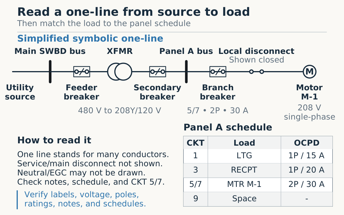
Begin at the utility source and move to the Main SWBD bus. The drawing then crosses a feeder breaker before reaching XFMR. The transformer changes the relationship from a 480 V primary to a 208Y/120 V secondary, so pause and orient the secondary before moving on.
From the transformer, follow the secondary through its breaker to Panel A bus. The small panel schedule in the example identifies circuit 5/7 as the circuit for motor M-1, with a two-pole, 30 A branch protective device. That schedule reference connects the distribution path to the correct branch.
The line continues through a local disconnect, shown closed, and ends at Motor M-1, labeled 208 V single-phase. “Shown closed” describes the drawing symbol, not the field condition. The disconnect is only a candidate isolation point until its identity, sources, lockability, and role in the employer’s procedure are confirmed.
Cross-reference the panel schedule and equipment documents
A panel schedule can state the panel name and location, source, voltage, phase, wire count, bus and main ratings, enclosure, short-circuit rating, circuit numbers, pole positions, breaker ratings, load descriptions, and calculated load information. Check that the circuit number, pole count, ampere rating, and load tag agree with the one-line. A mismatch is a question to resolve, not permission to choose the more convenient value.
At the load, continue to the equipment nameplate and manufacturer instructions. For a motor, compare voltage and phase, then locate the controller, overload protection, disconnect, and control drawing. For HVAC equipment, a mechanical schedule may provide electrical requirements that the one-line only references. For a transformer or panelboard, actual markings and installation instructions add ratings that a simplified drawing cannot carry.
Conductor notation also needs discipline. A note can encode the number of parallel sets, conductor count and size, neutral, equipment grounding conductor, material, insulation, raceway, or special construction. It is project shorthand - not a standalone design rule. Raceway fill, ampacity adjustment, parallel-conductor rules, grounding, neutral sizing, and phase arrangement require the applicable design and code analysis.
Know what still requires field verification
- Revision and scope: confirm that the sheet applies to the location, phase of work, and equipment being discussed.
- Identity: match tags and labels without assuming that similar adjacent enclosures are interchangeable.
- Actual sources: look for generators, alternate feeds, controls, stored energy, photovoltaic systems, batteries, UPS equipment, and backfeed paths.
- Ratings and settings: use equipment markings, approved studies, schedules, and manufacturer information rather than estimating from symbol size.
- Condition and configuration: a drawn switch position, tie, or disconnect state is not a live status indication.
- Conflicts: stop and seek clarification when the one-line, schedules, labels, or field installation disagree.
The goal is not to make the one-line carry every answer. It is to use it as the system map that tells you which question comes next. Read from source to load, cross-reference every handoff, and keep intended design separate from verified field condition.
Official sources and further reading
Use these links to locate current controlling information. Standards, regulations, local adoption, and manufacturer instructions can change.
- NFPA - NFPA 70, National Electrical Code developmentUse the edition adopted by the authority having jurisdiction for the work.
- NFPA - Understanding NFPA 70Official NEC learning and orientation material.
- UL Solutions - Panelboards guideProduct-category guidance that helps interpret panelboard markings and certification information.
- OSHA - Electrical safety and health topicsA drawing is not a substitute for required safe work practices and verification.